|
||
E-Zine June 2006
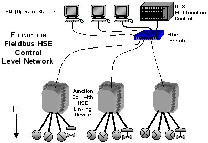
Click here to review Part 1 The initial ANSI/ISA 50.02 standard called for Fieldbus to have two-level architecture. The lower level (H1) provided the highest practical speed for an intrinsically safe environment while supplying power to the field devices. The upper level (H2) was intended to interconnect the H1 segments and aggregate the data for distribution to and from higher level systems. Implementation of H2 as specified in ANSI/ISA 50.02 and the IEC 61158-2 were found require custom chips that were more expensive than desired. In early 1998, the FOUNDATIONT Fieldbus HSE project was funded to specify low cost, high speed switched Ethernet appropriate for use in H2 service. Specifications for HSE were included in the IEC 61158 fieldbus standard as Type 5. HSE products are widely available and are being used to build process control systems based on FOUNDATIONT Fieldbus. As a result, many large and relatively complex systems are being installed at lower cost as compared to distributed control systems or FOUNDATIONT Fieldbus H1 systems. The cost savings for HSE is achieved by reducing the number of long wires (homerun cable) needed to connect the field H1 networks to the control room. The two-level FOUNDATIONT Fieldbus architecture utilizes Linking Devices (LD) to terminate H1 segments in the field. HSE cabling then runs from the LDs to the control room.
One of the primary motivations for the use of HSE is to better enable Field Control. Consider the case when HSE is not used, where each Fieldbus H1 segment terminates in the I/O unit of a multifunction controller. If a measurement value or cascade controller input is obtained from another H1 segment, there is no direct H1 path for the Fieldbus communications system to provide the link, so each controller must provide a software bridge to provide such links. However, the software bridge is not necessarily a real-time function, and may vary between different controller suppliers and designs, or may not be provided. Most control systems either do not allow or caution against making connections through a controller in this manner. Excerpted from The Consumer Guide to Fieldbus Network Equipment for Process Control ISSN 1538-5280 |
||