|
||
E-Zine April 2010
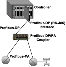
Click here to review Part 1 PROFIBUS-PA was built on the backbone of PROFIBUS-DP which was created to provide the data transfer needs for factory automation and materials handling in discrete parts manufacturing. It was designed to be the communications network for linking programmable logic controllers (PLC) together and with host computer systems and Human Machine Interface (HMI) used in the factory. However, the need to connect process control instrumentation has been a mission of the PNO (PROFIBUS Nutzerorganisation), the development group of PROFIBUS International. In general, PROFIBUS-PA was developed to meet the needs of the process industries that did not want or need Field Control. PROFIBUS-PA was originally designed to have a two-level bus hierarchy. Both bus levels run the same protocols, but use different physical means to enable different bus speeds. PROFIBUS-PA uses the identical physical layer as FOUNDATION™ Fieldbus H1 that is specified in ANSI/ISA 50.02 Part 2 and IEC 61158 Part 2, Type 1. This enables bus power and intrinsic safety for process control applications. The upper level bus is PROFIBUS-DP using RS-485, as specified in IEC 61158-2. No direct controller interface for PROFIBUS-PA is required since it is interfaced via a PROFIBUS-DP compatible RS-485 port. A PROFIBUS-DP/PA linking device or segment coupler is used to connect each PA segment to a DP bus. PROFIBUS-DP typically supplies power to each PA segment through the bus coupler or linking device.
The bus master, typically a multifunction controller, controls all data transmissions on PROFIBUS. Transmissions on PROFIBUS are asynchronous, so the controller itself synchronizes all of its own control loops. However, field instruments may execute local functions such as signal processing and alarm limit checking to off-load these functions from the shared controller. The basic configuration of each field device is contained in a GSD (Gerätestammdaten: equipment master data) record published by the device supplier. In addition, each device may also process its data using an EDD (Electronic Device Description) produced and downloaded to the device. The EDD contains the specific database used by the device to process the raw measurement signals and check for alarm limit violations. The original form of EDD was proprietary for each device supplier, but they are now standardized by IEC 61804 Function Blocks for Process Control so that they will become uniform across suppliers. EDDs will be functionally similar to, but not exactly the same as, the signal processing Device Descriptions for FOUNDATION™ Fieldbus and HART. Excerpted from The Consumer Guide to Fieldbus Network Equipment for Process Control ISSN 1538-5280 |
||


