|
||
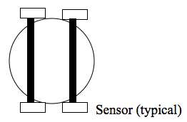
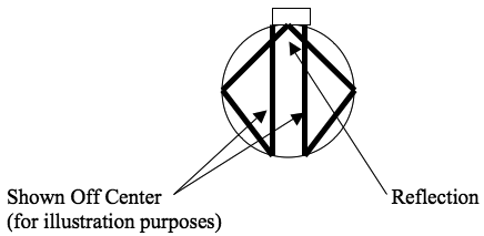
E-Zine July 2010In some installations (especially with smaller pipe sizes), the transit time can be so short as to limit the ability of the transmitter to accurately measure flow. To increase the transit time, some ultrasonic flowmeter utilize multiple traverses that effectively increase the path length by bouncing ultrasonic energy off the inside pipe wall (see figures below). Losses due to attenuation at the point of reflection generally increase the amount of ultrasonic energy required (as compared to designs with no reflections).
Some ultrasonic flowmeters locate the ultrasonic energy along a chord of the pipe. In these designs, the ultrasonic energy path is located off-center and does not travel through the center of the pipe. By doing so, the relatively high velocity at the center of the pipe is avoided.
Various combinations of the above path geometries are also available. In addition, some multiple traverse ultrasonic flowmeters use smooth surfaces in the flowmeter to reflect the ultrasonic energy in a manner that samples more of the flowing stream.
Excerpted from The Consumer Guide to Ultrasonic and Correlation Flowmeters ISSN 1538-5280 |
||


