TECHNICAL AND MARKETING SERVICES
FOR INSTRUMENTATION SUPPLIERS AND END-USERS
Ultrasonic Level Measurement (Part 2 of 3)by David W Spitzer and Walt Boyes
Many ultrasonic sensors have integral temperature sensors to compensate for the effects of vapor temperature on the measurement. Recognizing that the sensor temperature may not be representative of the vapor temperature in the vessel, some ultrasonic level gauges can use external vapor-space temperature measurement(s) for compensation.
Noting that the ultrasonic energy travels to and returns from the material, attenuation between the sensors and the material can cause ultrasonic level measurement systems to fail. Degradation can occur at the sensors, in transit to/from the material, and at the surface of the material.
The design of the ultrasonic sensors is important. In particular, dirt or other coatings on ultrasonic sensing system can cause the emitted and received ultrasonic signals to be weak. As the signals become weaker, the measurement system can become erratic and fail to operate. When accumulations over time are normal for the process, routine maintenance may be required to keep the sensors operating.
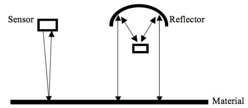
Careful analysis of the sensor design should be performed. Some designs inherently tend to maintain the sensor clean while others tend to inherently accumulate material. For example, the sensor system on the right in the figure emits ultrasonic energy upward to a reflector that redirects the energy down to the material. In this design, material can accumulate on the sensors and stick to the reflector. Both of these phenomena can attenuate ultrasonic energy and cause the level measurement system to fail to operate.
Excerpted from The Consumer Guide to Non-Contact Level Gauges.
Of Turndown & Velocity: What Flowmeter Turndown Mean in Terms of Flowrateby David W Spitzer
Last month we discussed how claims of high turndown imply a wide range of flows.In particular, a turndown of 1000:1 for a magnetic flowmeter implies measurements between velocities of 0.01 and 10 meters per second.However, most applications tend to require turndowns of approximately 10:1 or less.Turndowns above 10:1 would be better, but the following questions come to mind.
What do the higher turndowns mean in terms of flow (velocity)?
Will the process ever operate at these flow rates (velocities)?
Flowmeters are often sized such that the liquid velocity at full scale flow is approximately 2-3 meters per second. A turndown of 10:1 implies that a typical flowmeter will operate properly from (say) 0.25 to 2.5 meters per second. Increasing the turndown to 100:1 implies that the flowmeter will improve operation from (say) 0.025 to 2.5 meters per second. This turndown (100:1) is 10 times better, but the actual difference is the coverage of the velocities between 0.025 to 0.25 meters per second. This is a relatively small flow range, but it could be important in some applications. Further improving the turndown to 1000:1 would allow improved measurement between 0.0025 and 0.025 meters per second. This represents another improvement, but it similarly applies to a small part of the flow range.
Will the process ever operate at the flow rates (velocities) covered by the improved turndown specifications? In some applications, the answer is absolutely "yes". However, in most applications, the process does not operate in these relatively small flow ranges of increased turndown... and if it does, flowmeter accuracy is not the prime concern. This is not to say that turndown is not important --- it is. But accurate measurement may not be the biggest problem when the process operates in upset conditions only (say) 0.1 percent of the time.
Let's integrate turndown and accuracy next month.
This article originally appeared in Flow Control magazine.
Matching the Transmitter to Maximum Capsule Span by David W Spitzer
A primary flow element generates 0 to 150 inches of water column differential at maximum flow.Presuming similar design and manufacture, which of the following capsules with the following (hypothetical) maximum spans should be selected?
A. 0-130 inches of water column
B. 0-150 inches of water column
C. 0-200 inches of water column
D. 0-250 inches of water column
The differential pressure flow transmitter should be calibrated for 150 inches of water column.Even though it might be possible to calibrate Transmitter A to 0-150 inches, the maximum capsule span should be larger than the calibration.Transmitter A will likely not be accurate.
The maximum span for Transmitter B matches the primary flow element requirement while Transmitters C and D can be calibrated to 0-150 inches of water column. Therefore, Transmitters B, C and D could legitimately be selected.
However, it would be appropriate to gather more information about the application in order to select the best transmitter. For example, will the process be expanded to (say) double its existing capacity? If so, Transmitter D might be the best selection so as not to have to purchase a new transmitter during the expansion.
Given that the maximum capsule span should be higher than the calibrated span and that the transmitters are of similar manufacture and design, superior flowmeter performance is usually achieved by selecting the capsule that is as close as practical to the calibrated span. In this application, Transmitter B should be selected because it is equal to the calibration.
Additional Complicating Factors
The above analysis is quite cursory in nature. More detailed analysis of the accuracy, temperature effect, and pressure effect should be performed to quantify the improved accuracy of Transmitter B. Further complication will occur when comparing differential pressure transmitters of different design and manufacture.
This article originally appeared in Flow Control magazine.
ABOUT SPITZER AND BOYES, LLC
In addition to over 40 years of experience as an instrument user, consultant and expert witness, David W Spitzer has written over 10 books and 500 articles about flow measurement, level measurement, instrumentation and process control. David teaches his flow measurement seminars in both English and Portuguese.
Spitzer and Boyes, LLC provides engineering, technical writing, training seminars, strategic marketing consulting and expert witness services worldwide.
ISSN 1538-5280
Copyright 2025 Spitzer and Boyes, LLC
The content of this message is protected by copyright and trademark laws under U.S. and international law. All rights reserved.